
So I used the Arduino as a PWM driver for 8 RGB or 24 (3*8) white LEDs.
ARDUINO TIMER INTERRUPT PIN 2 DRIVERS
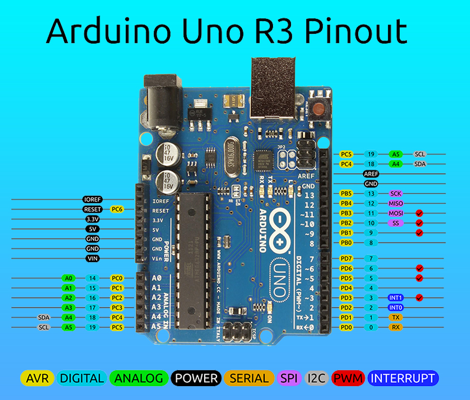
I also don't know exactly what the proper keywords are that I need to find the relation between timers and pins.Īs I for now just got some stuff from my local dealer I have no access to shift registers, PWM drivers and other proper integrated circuits. Copy Code // Timer0 is already used for millis () - we'll just interrupt somewhere // in the middle and call the 'Compare A' function below OCR0A 0xAF TIMSK0 BV (OCIE0A) Then we'll define an interrupt handler for the timer interrupt vector known as 'TIMER0COMPAvect'. For example, if you connect to pin 3, use digitalPinToInterrupt (3) as the first parameter to attachInterrupt (). Normally you should use digitalPinToInterrupt (pin) to translate the actual digital pin to the specific interrupt number. I cannot find any information about the Arduino Micro. The first parameter to attachInterrupt () is an interrupt number. Most simple things work on all devices, but if you start with complex code to fasten up things, every device is a little different.Ī problem I could not solve for days now is the relation between pins and timers.

I'm planning to also get a Mega and others.

IRQ pins (or Interrupt pins): Klipper does not use hardware. The one I mostly use is the Uno and Micro for now. In particular the Arduino pin numbers frequently dont translate to the same hardware names. Where do I find the pins relative to timers of each individual Arduino microcontroller?Īs I like Arduino's I already have various samples of them.


 0 kommentar(er)
